
I long ago found this post about hacking digital multimeters to access new features and I have wanted to try it out for years now. In particular, Kerry Wong was able to enable the multimeter's serial output which is useful for data logging or otherwise injecting that data into some other computer. This is my attempt to recreate the same hack. I don't have the same multimeter, and the chip on my multimeter isn't marked in any way as a DTM0660L, but the package is the same and given the datasheet that Kerry translated and tracing out where some of the pins go, it really seems like this is the same or a very similar chip.
First, I did some data gathering. Below are my composite photos of the board flipped and roughly persepctive corrected so that they roughly line up if you layer them in, say, Gimp. It is 2-layer, has a processing chip and a 256-byte EEPROM. It also has several unpopulated headers near the EEPROM (J1 and J3) and what looks to be an unpopulated serial Rx/Tx header down by the beeper (J2). I soldered headers to these after confirming that I can still close the case with them attached. I used right angle pins for the serial header as I saw that I couldn't close the case if I connected wires to a those.

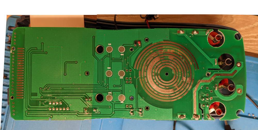
Note that you also need to worry about room on the other side of the board. Immediately below J1 and J3 is the backlight for the LCD. After I soldered the pin headers, I clipped the bottom pins flush with the board and then reflowed each pin so the result is mostly flush and smooth. No need to worry about that for the J2. It looks like J1 is a header for programming the main control chip. J2, is for serial data out (and perhaps in). J3 is an EEPROM programming header.
Used my cheapo logic analyzer with Sigrok/PulseView to capture some traffic to/from the EEPROM.

In general I wanted to make sure we don't interfere with the meter reading from the EEPROM. However, looking at when data is transferred, this isn't much of a problem. Data is only read when you interact with the meter (i.e. pressing buttons or changing the mode). The rest of the time, the I2C bus is completely silent.
Used my Bus Pirate to dump the EEPROM in total. This is done by connecting ground to the Bus Pirate (first pin to brown lead), connecting VCC from EEPROM to the pull-up on the Bus Pirate (second pin to green lead), serial clock to serial clock (third pin to purple), and serial data to the serial data (fourth pin to gray).
In order to read from the device with the Bus Pirate, we need to use the funky Bus Pirate command line scripting syntax.
My pin states look like this.
I2C>v
Pinstates:
1.(BR)  2.(RD)  3.(OR)  4.(YW)  5.(GN)  6.(BL)  7.(PU)  8.(GR)  9.(WT)  0.(Blk)
GND     3.3V    5.0V    ADC     VPU     AUX     SCL     SDA     -       -
P       P       P       I       I       I       I       I       I       I
GND     0.00V   0.00V   0.00V   3.01V   L       H       H       H       H
You can then do a scan from the Bus Pirate to find the EEPROM using one of the predefined I2C macros:
I2C>(0)
 0.Macro menu
 1.7bit address search
 2.I2C sniffer
I2C>(1)
Searching I2C address space. Found devices at:
0xA0(0x50 W) 0xA1(0x50 R)
Very handy, that macro. We need to write the address to read from, then read 256 bytes (the size of the EEPROM). First, write the address to read from by starting an I2C message with '[', writing the I2C write address of the EEPROM, then writing the address to read from (0 in this case), and finally close out the I2C message with ']'.
I2C>[0xa0 0]
I2C START BIT
WRITE: 0xA0 ACK
WRITE: 0x00 ACK
I2C STOP BIT
Then we need to read the data. This time we write the read address, and read a byte (and repeat that 256 times with ':256').
I2C>[0xa1 r:256]
I2C START BIT
WRITE: 0xA1 ACK

READ: 0xFF ACK 0xFF ACK 0xFF ACK 0xFF ACK 0xFF ACK 0xFF ACK 0xFF ACK 0xFF ACK
0xFF ACK 0x52 ACK 0x00 ACK 0x5E ACK 0x01 ACK 0x20 ACK 0xF5 ACK 0x03 ACK 0x06 ACK
0x20 ACK 0x38 ACK 0x18 ACK 0x44 ACK 0x02 ACK 0x6E ACK 0x4B ACK 0xC8 ACK 0xC8 ACK
0xFF ACK 0xFF ACK 0x14 ACK 0xFF ACK 0x40 ACK 0xFF ACK 0xF7 ACK 0x99 ACK 0xE7 ACK
0x7F ACK 0x64 ACK 0x00 ACK 0x96 ACK 0x00 ACK 0x00 ACK 0x80 ACK 0x82 ACK 0x80 ACK
0x62 ACK 0x80 ACK 0x0C ACK 0xE7 ACK 0x4E ACK 0x02 ACK 0x09 ACK 0x37 ACK 0xFA ACK
0x08 ACK 0x3A ACK 0x04 ACK 0x0B ACK 0xFA ACK 0x1A ACK 0x0A ACK 0x09 ACK 0xFC ACK
0x09 ACK 0x00 ACK 0x00 ACK 0x01 ACK 0x00 ACK 0x01 ACK 0x00 ACK 0x07 ACK 0x98 ACK
0x00 ACK 0x64 ACK 0x00 ACK 0x64 ACK 0x00 ACK 0x64 ACK 0x00 ACK 0x00 ACK 0x00 ACK
0x00 ACK 0x80 ACK 0x00 ACK 0x80 ACK 0x00 ACK 0x80 ACK 0x00 ACK 0x80 ACK 0x00 ACK
0x80 ACK 0x00 ACK 0x80 ACK 0x00 ACK 0x80 ACK 0x00 ACK 0x80 ACK 0xC0 ACK 0x7F ACK
0x00 ACK 0x83 ACK 0x01 ACK 0x00 ACK 0x09 ACK 0x2B ACK 0x00 ACK 0x00 ACK 0x00 ACK
0x00 ACK 0x00 ACK 0x00 ACK 0x00 ACK 0x00 ACK 0x0A ACK 0x80 ACK 0x00 ACK 0x80 ACK
0xFA ACK 0x86 ACK 0xE0 ACK 0x7C ACK 0x18 ACK 0x01 ACK 0x00 ACK 0x00 ACK 0x00 ACK
0x00 ACK 0x00 ACK 0x00 ACK 0x00 ACK 0x00 ACK 0x00 ACK 0x13 ACK 0x00 ACK 0x1B ACK
0x0E ACK 0x0C ACK 0x00 ACK 0x0B ACK 0x10 ACK 0x12 ACK 0x07 ACK 0x14 ACK 0x06 ACK
0x05 ACK 0x00 ACK 0x00 ACK 0x00 ACK 0x15 ACK 0x00 ACK 0x00 ACK 0x0F ACK 0x0D ACK
0x00 ACK 0x00 ACK 0x11 ACK 0x00 ACK 0x09 ACK 0x00 ACK 0x00 ACK 0x00 ACK 0x00 ACK
0x00 ACK 0x00 ACK 0x00 ACK 0x00 ACK 0x00 ACK 0x00 ACK 0x00 ACK 0x00 ACK 0x00 ACK
0x00 ACK 0x00 ACK 0x0A ACK 0x00 ACK 0x00 ACK 0x00 ACK 0x00 ACK 0x00 ACK 0x00 ACK
0x00 ACK 0x00 ACK 0x00 ACK 0x00 ACK 0x00 ACK 0x00 ACK 0x00 ACK 0x00 ACK 0x00 ACK
0x00 ACK 0x00 ACK 0x00 ACK 0x00 ACK 0x0D ACK 0x00 ACK 0x02 ACK 0x10 ACK 0x0D ACK
0x00 ACK 0x03 ACK 0x20 ACK 0x20 ACK 0x00 ACK 0x03 ACK 0x20 ACK 0x20 ACK 0x00 ACK
0x03 ACK 0x10 ACK 0x41 ACK 0x00 ACK 0x03 ACK 0x08 ACK 0x41 ACK 0x00 ACK 0x03 ACK
0x05 ACK 0x41 ACK 0x00 ACK 0x03 ACK 0x05 ACK 0x0D ACK 0x00 ACK 0x02 ACK 0x20 ACK
0x00 ACK 0x80 ACK 0x00 ACK 0x80 ACK 0x00 ACK 0x80 ACK 0x00 ACK 0x80 ACK 0x00 ACK
0x80 ACK 0x00 ACK 0x80 ACK 0x00 ACK 0x80 ACK 0x00 ACK 0x80 ACK 0x00 ACK 0x80 ACK
0xFF ACK 0xFF ACK 0xFF ACK 0xFF ACK 0xFF ACK 0xFF ACK 0x5A ACK 0xC7 ACK 0x4C ACK
0x0F ACK 0x0F ACK 0x92 ACK 0x00 ACK 0x00

NACK
I2C STOP BIT
(Note that I broke the lines in the 'READ' output for readability). We can use some standard tools to make this a bit easier to read. Passing through:
sed 's/ACK//g' | xxd -r -p | xxd
…produces…
00000000: ffff ffff ffff ffff ff52 005e 0120 f503  .........R.^. ..
00000010: 0620 3818 4402 6e4b c8c8 ffff 14ff 40ff  . 8.D.nK......@.
00000020: f799 e77f 6400 9600 0080 8280 6280 0ce7  ....d.......b...
00000030: 4e02 0937 fa08 3a04 0bfa 1a0a 09fc 0900  N..7..:.........
00000040: 0001 0001 0007 9800 6400 6400 6400 0000  ........d.d.d...
00000050: 0080 0080 0080 0080 0080 0080 0080 0080  ................
00000060: c07f 0083 0100 092b 0000 0000 0000 0000  .......+........
00000070: 0a80 0080 fa86 e07c 1801 0000 0000 0000  .......|........
00000080: 0000 0013 001b 0e0c 000b 1012 0714 0605  ................
00000090: 0000 0015 0000 0f0d 0000 1100 0900 0000  ................
000000a0: 0000 0000 0000 0000 0000 0000 0a00 0000  ................
000000b0: 0000 0000 0000 0000 0000 0000 0000 0000  ................
000000c0: 0d00 0210 0d00 0320 2000 0320 2000 0310  .......  ..  ...
000000d0: 4100 0308 4100 0305 4100 0305 0d00 0220  A...A...A......
000000e0: 0080 0080 0080 0080 0080 0080 0080 0080  ................
000000f0: 0080 ffff ffff ffff 5ac7 4c0f 0f92 0000  ........Z.L.....
By the way, this is my first time using the Bus Pirate and I have to say that I like the scripting language/command interface. It certainly made this process much less painful than my original plan which was to use an arduino to interface with the IC. I can just interactively pull the data off the chip with no programming at all.
According to Kerry's notes, my EEPROM has some significant differences, but the basic structure seems pretty much the same. The data I want to change is in the last line there. In particular, I want to change the value at 0xfa from 0x4c to 0x4e in order to enable RS232 output and 0xfc to 0x00 in order to disable backlight timeout (if I turn it on, I'll be responsible to turn it off) but I'll leave the auto-power off timer at 15 minutes as I cannot tell you how often I don't turn off my meter and hear it beeping from the other room.
As an aside, another hack that I found necessary with this meter is a mechanical one. I stuck hot glue in the beeper as it was much too loud. Even with the glue in place and the beeper sounding comically puny, I can still hear it from the other room. At least this won't wake up the family in the middle of the night.
In order to actually write to the EEPROM, you need to pull the write protection (WP) pin low. This pin is connected to the Rx pin in the serial header by the beeper. So jump that over to ground somewhere. This brings up a worry I had throughout this effort probably due to my relative inexperience with electronics, how do I know that it is safe to connect two areas in a circuit? If I connect two parts of the circuit which are held at different voltages, a current will flow which could damage components. For instance, how do I know that I can connect the Rx pin to ground? In this case we can guess it is safe due to two observations:
- The pin seems to be a receive pin, meaning it is set in input, or high impedance, mode. This means that the main IC is not driving this pin high.
- The pin seems to be pulled high via a 10k resistor.
As for the other connections in the system, this EEPROM is an I2C device, which means that the bus is all open-drain. This is an inherently safe bus as nothing ever drives the bus high, it only pulls it low. Any non-zero voltage is due to pull-up resistors on the bus.
Quick note, in case it isn't obvious (it wasn't to me at first), while it might seem tempting you cannot reliably probe around the multimeters circuitry using the meter itself... I learned that after many confusing measurements. You will likely need a separate multimeter if you want to mess around with this. Luckily I had one, unluckily it is from circa 1980 with broken leads, so it is not a joy to use.
Getting back to it, we issue the commands to write our new configuration:
I2C>[0xa0 0xfa 0x4e 0x0f 0x00]
I2C START BIT
WRITE: 0xA0 ACK
WRITE: 0xFA ACK
WRITE: 0x4E ACK
WRITE: 0x0F ACK
WRITE: 0x00 ACK
I2C STOP BIT
I2C>[0xa0 0xfa]
I2C START BIT
WRITE: 0xA0 ACK
WRITE: 0xFA ACK
I2C STOP BIT
I2C>[0xa1 r:256]
I2C START BIT
WRITE: 0xA1 ACK
READ: 0x4E  ACK 0x0F  ACK 0x00 ACK ....
NACK
I2C STOP BIT
And… voila, it is done. Power cycle the unit but make sure to disconnect the ground jumper to the Rx line or the multimeter will enter some kind of calibration/test mode.
A quick check shows that if I hold the backlight button to turn it on, it stays on for as long as I was willing to test it (several minutes). When I hold the relative button which should activate serial output, I see different behavior which tells me that something changed, but I cannot get any serial output still. With the previous value of 0x4c which should disable UART output, pressing relative (even if attempting to hold the button) the unit will beep immediately, setting relative mode at the key down event. With the new value of 0x4e, it doesn't beep/set relative immediately, and after about a second of holding it will beep and not set relative mode. There is no indication on the LCD, but that might just be because there is no spot for it. Whatever the case, I cannot see any data on any pin I probe. I would expect it to be on the Tx pin but I only see 0 V on that pin. Of course sigrok-cli doesn't have some magic in it to decode a steady 0 V into meaningful data.
After 'enabling' UART output with a long press and a beep, I probed around on the board to see if there was any steady stream of data anywhere, but saw nothing on any pins. I also noted the disconnected solder bridge connected to the Rx line. If I bridge that, it just pulls Rx low which will enable EEPROM write and also force the weird calibration/test mode on startup. I don't think that is useful for this.
Unfortunately, while the EEPROM change worked as it successfully changed the behavior of the backlight, the ultimate goal of serial output failed. If anyone reading this can see what I'm doing wrong or has some ideas of what to try, please let me know. I would love to have this data for a project I'm working on. Perhaps I'll just end up buying a DMM which has this feature already enabled… but where is the fun in that? I also could decode the signals sent to the LCD and turn that into data for a serial console to receive, but that sounds like even less fun.